 |
| The bottom view of the PCB circuit |
Project Work
Tuesday, 5 February 2013
Connecting the PCB circuit & Battery & Servo
Sunday, 27 January 2013
Modification to our servo bracket
 |
| Servo bracket Before modification |
 |
| Servo bracket After modification |
 |
| Servo bracket screwed on to the side of the Drawer beside the lock |
The servo bracket was also placed just nice so there will be no obstruction when the arm axle turn.
Saturday, 26 January 2013
Wire clips and Battery compartment
 |
| Wire clips |
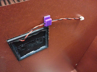
We made these wire clips to neatly hold the wires on the surface of the drawer interior. Without these, the wires would be in a mess and may be damaged when the drawer is in use.
 |
| Image of Battery Holder firmly glue on to the Drawer |
Friday, 25 January 2013
Uses of Ribbon in the Battery Case
To simplify the battery removal
process, a ribbon was glued together on the battery casing. To remove the
batteries, pulling the ribbon and it will eject them.
The picture above show us how the battery can be easily remove , just by pulling the ribbon.
 |
| Before the battery has been pull out |
 |
| Last battery remaining before pulling out just by easily pulling the ribbon |
Battery Holder place on the Drawer with battery and cover
 |
| Before the Process |
 |
| 2 of the component is glue together using insta-flex+- |
 |
| After the glue has dry up , the battery cover will be place in the middle and glued up |
 |
| Battery Holder with Battery and Cover nicely glue onto the Drawer |
Thank to Mr Khiew, he help us on design and cut the "smiley face" battery cover using LPKF rapid prototyping milling machine. The "mouth slot" is for user to pull up the cover easily in order to replace a new battery. The picture above show the complete assembly of the battery compartment.
Mounting on Battery case to the Battery Holder (Without Battery)
How Battery Holder Look like Part by Part
Subscribe to:
Comments (Atom)


