Sunday 27 January 2013

Modification to our servo bracket

Servo bracket Before modification
Servo  bracket After modification

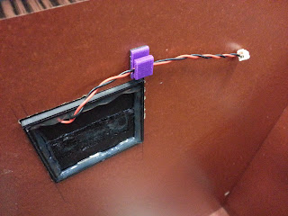
Servo bracket screwed on to the side of the Drawer beside the lock

We made modification to the servo bracket. Instead on using double sided tape to tape the bracket onto the drawer , we make the bracket longer so that we can screw in the holder.
The servo bracket was also placed just nice so there will be no obstruction when the arm axle turn.


Saturday 26 January 2013

Wire clips and Battery compartment

Wire clips
We made these wire clips to neatly hold the wires on the surface of the drawer interior. Without these, the wires would be in a mess and may be damaged when the drawer is in use.
Image of Battery Holder firmly glue on to the Drawer 
This show the battery compartment after it has been glue to the drawer. We also use the wire clip to hold up the wires so that it wont be messy and dangling around .

Friday 25 January 2013

Uses of Ribbon in the Battery Case

To simplify the battery removal process, a ribbon was glued together on the battery casing. To remove the batteries, pulling the ribbon and it will eject them. 
Before the battery has been pull out
Last battery remaining before pulling out just by easily pulling the ribbon 

The picture above show us how the battery can be easily remove ,  just by pulling the ribbon.

Battery Holder place on the Drawer with battery and cover

Before the Process
Each component is place neatly before the process
2 of the component is glue together using insta-flex+-
The component is glue together using insta-flex+- and chip to hold them firmly

After the glue has dry up , the battery cover will be place in the middle  and glued up
& Finally~~

Battery Holder with Battery and Cover nicely glue onto the Drawer

Thank to Mr Khiew, he help us on design and cut the "smiley face" battery cover using LPKF rapid prototyping milling machine. The "mouth slot" is for user to pull up the cover easily in order to replace a new battery. The picture above show the complete assembly of the battery compartment.


Mounting on Battery case to the Battery Holder (Without Battery)

Battery Case Mounted on the Battery Holder
We use hot glue to glue the battery case as hot glue is faster and stronger. The ribbon inside the battery case is there so that the battery can be easily pull out with ease.

How Battery Holder Look like Part by Part

Battery Holder Frame


Support for the Battery


Holder for the Slide Cover


After Every Component has been glue together 
This show how the battery holder look like before everything is assemble together

Thursday 24 January 2013

Final Product & Placing in on the Drawer Roof

End Product (After Modification)
Finally , the PCB holder is done decorating with the help by our lectureer. The Cover was send for lamination before pasting on the Frame holder using double side tape.
The purpose of doing so was that the cover will have a smooth and even surface as we switch to
countersink screws which do not bulge on the surface.The dark transparency helps to keep the screw-holes almost unnoticeable.

Comparison between the old & new frame holder

Old Frame Holder 
Material use
- 2 layer of clear transparency
- 1 layer of paper printed with keypad number
- 7 plastic screw

New Frame Holder

Master use
- 1 layer of dark transparency 
- 1 small paper printed with keypad number
- 7 countersink screws

Cutting of Battery Holder hole on the Drawer

Picture of the Battery holder hole being cut
This picture show my teammate cutting the battery holder hole after much measurement and calculation for the placement of the hole.

Wednesday 23 January 2013

End Product without Modification

End Product (Before Modification)
After printing and getting all piece together , this is the End Product we have.
But the appearance is still not satisfying ,  as the screw can be seen and it doesn't make up with the black background of the cover. Although we add in transparent sheet to enhance the appearance , but it does not seem to work well.

Number Pad cover for the KeyPad

KeyPad Cover along side the PCB
We printed out a cover for the keypad so that we actually know which button we are pressing and which button can use for programming later on.

Tuesday 22 January 2013

Puting the PCB and Frame together

Our PCB circuit Frame Holder(Without PCB circuit)
Frame Holder Together With PCB Circuit

This is the picture of the PCB circuit and Frame after putting together. Next we will do some decoration to make it look nicer.

Soldering of PCB circuit component on to the PCB circuit

Before component are solder on to the PCB circuit 

Process of the component bring solder on to the PCB circuit
Most of the component have been solder on to the PCB circuit
How the Circuit will roughly look like after all the component have been solder on to the Board

Monday 21 January 2013

Datasheet for the 7-Digit 7-Segment LED display

DataSheet of the 7-Digit 7-Segment LED Display


Some hardware & what are their uses

7-digit 7-segment LED display + LED light
  ~ for displaying information to users
  ~ more compact than 7 separate LED  display
  ~ only uses 14 pins


16x Tactile Push Button 
  ~ for the keypad
  ~ using 4X4 small tactile push buttons instead of a whole keypad


USB mini 
  ~ input program into PCB

ATMEGA32U4
  ~ to run program 
  ~ store memory

Wednesday 2 January 2013

Mounting & Cutting of Drawer for Frame


Once the frame was complete, we went on to dismantle the drawer for cutting and drilling.

dismantled drawer..

After cutting..
Trying to see our Frame holder fit the hole 
Perfect fit!